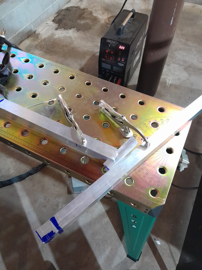
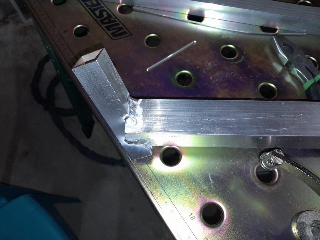
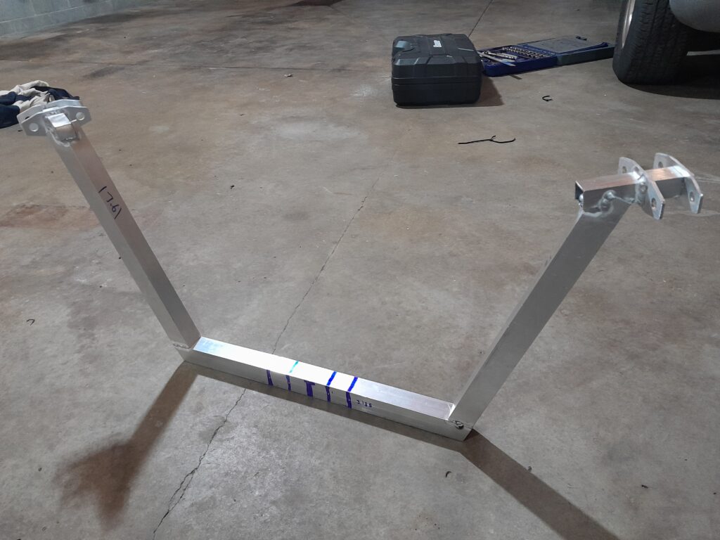
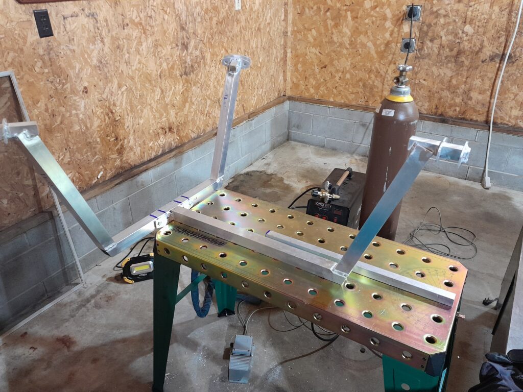
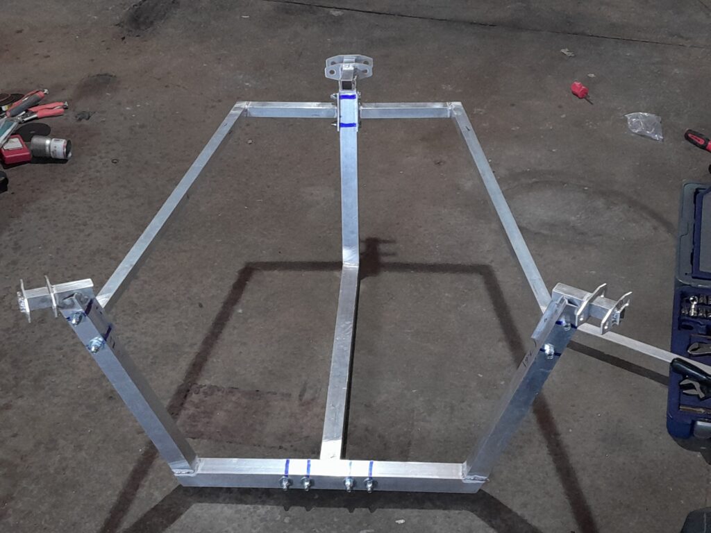
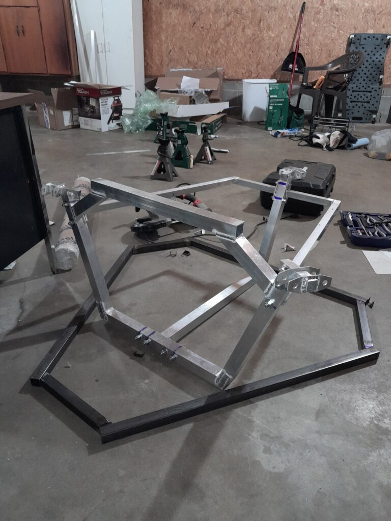
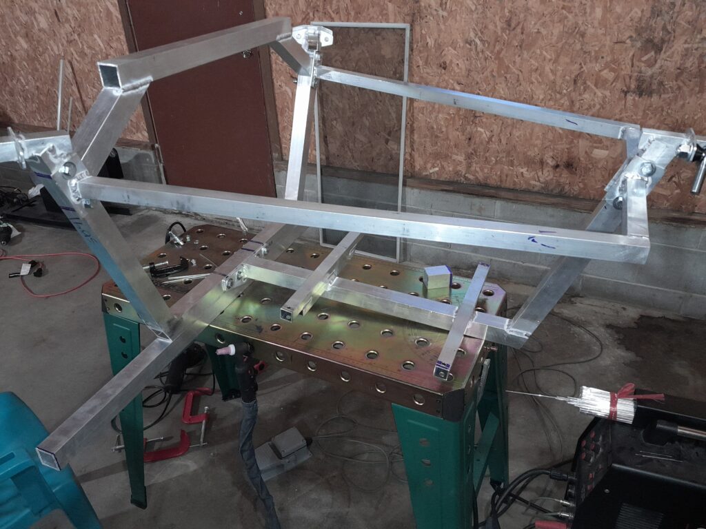
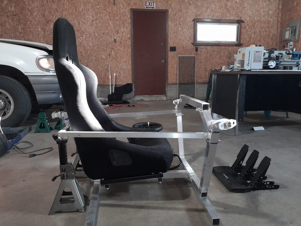
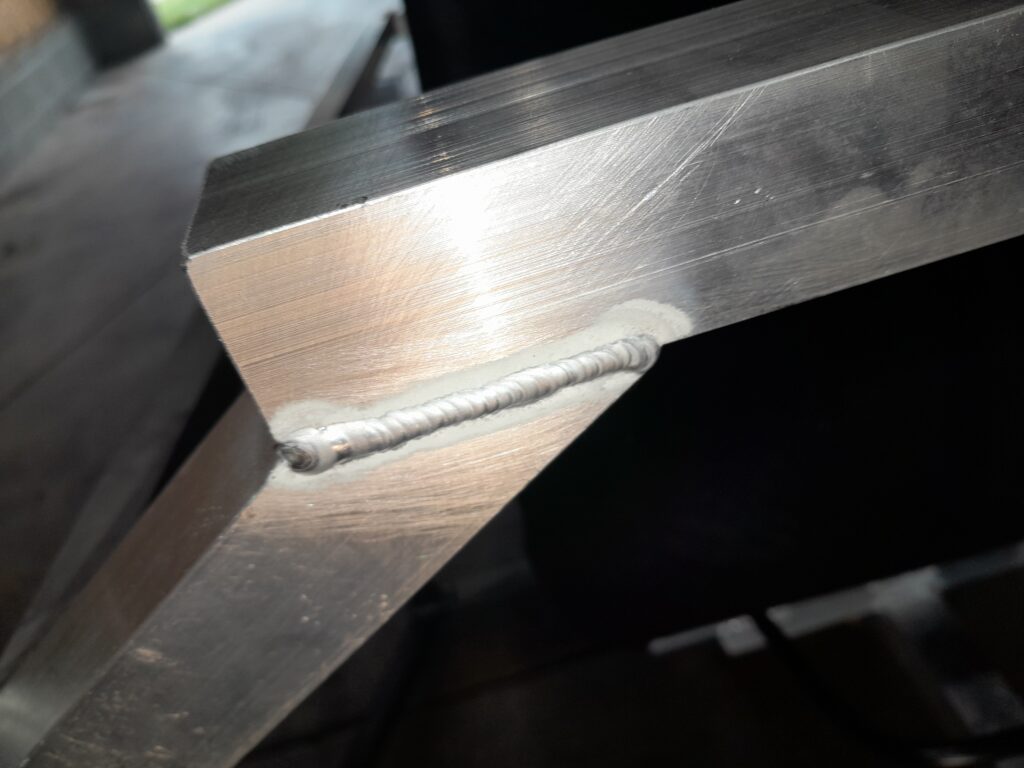
Fabrication of the driver frame. All frame members are TIG welded. The main frame is made from 1 1/2″ 6063 aluminum square tubing.
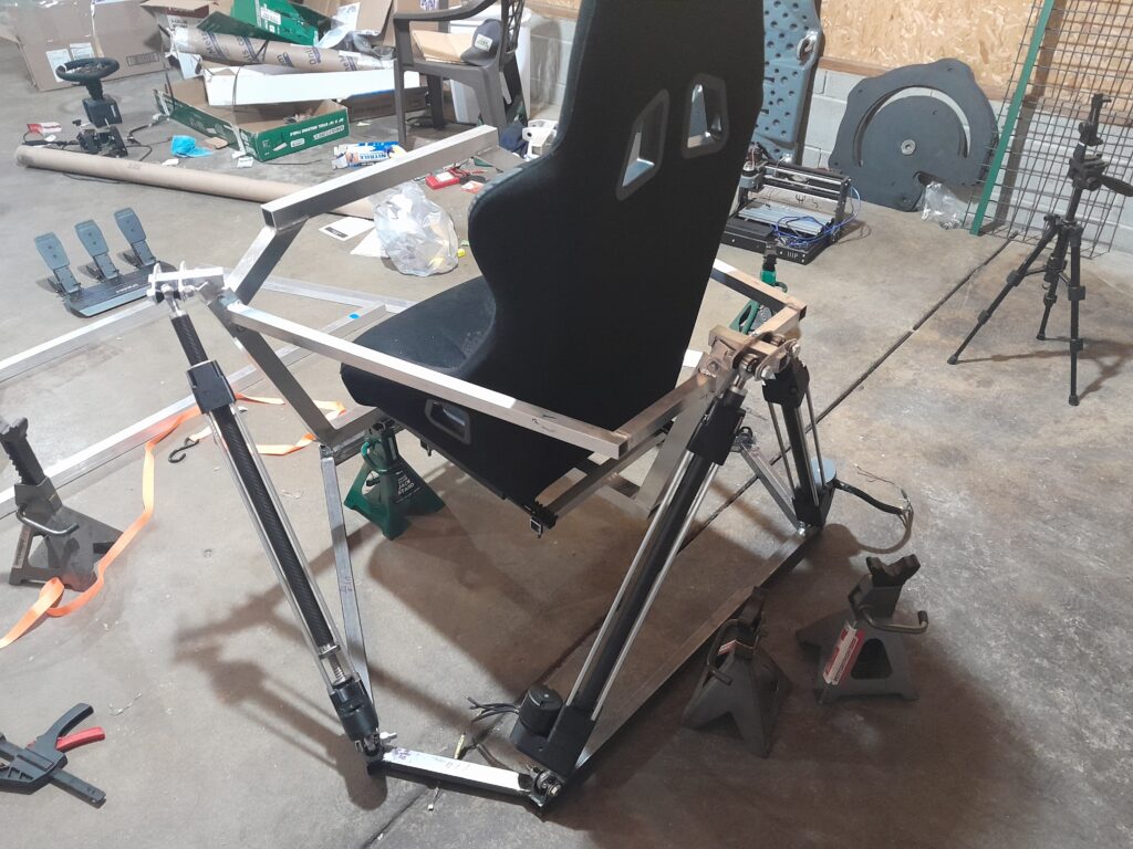
Further progress on completing the actuators. I was constantly 3D printing and turning over 50 parts on a manual mini lathe when this picture was taken. I could not wait to have all six actuators complete so I could see my creation moving.
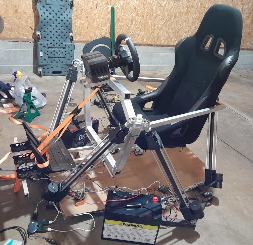
All actuator parts are completed at this point. At this point I was configuring the motor drivers and tuning the reverse kinematic program for the range of the actuators and the motion limits of the complete system.
Testing motion capabilities and endurance. Work on the peripheral mounting is nearly done. The only remaining fabrication are tabs to connect the pedal structure to the main driving frame using 3/8″ threaded rod.
Testing with full body weight. Larger pulleys were ordered for a larger reduction from the motor to the ball screw. The rear motors struggle to move with most of the weight biased towards the rear and the reduction should help as the motors are not limited on speed currently. This test is when I decided to increase the ball screw pulley tooth count while sacrificing some speed of the actuator.
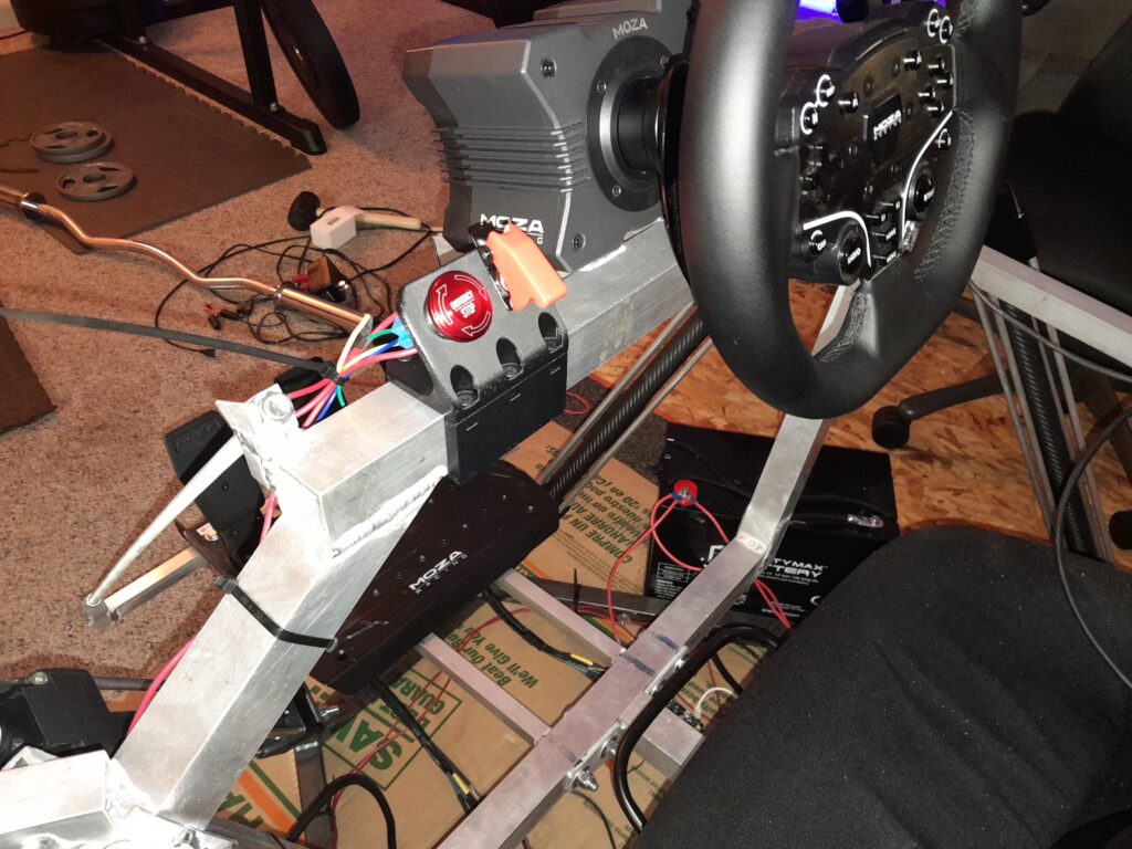
3D printed switch panel including an emergency stop button wired to high current relays.